grease trap diagram
Create a grease trap diagram. Grease traps usually consist of an underground watertight concrete tank with baffled inlet and outlet piping.
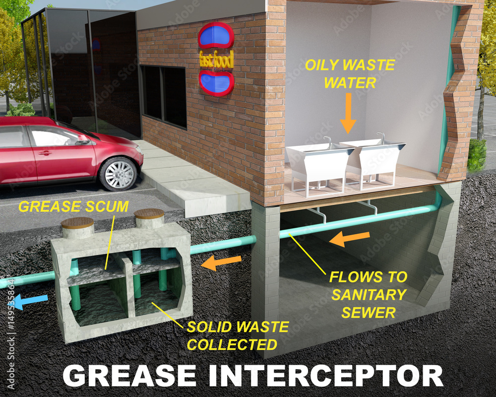
Grease Interceptor Grease Trap Illustration Diagram Stock Illustration Adobe Stock
Water temperatures must be less than 120.
. From sinks and dishwashers to allow for adequate cooling of the wastewater. 25 GPM Grease Trap CAD Drawings Zip. 20 GPM CAD Drawings Zip file.
Shipping Returns Policy. Install grease absorber in grease trap if included then snap cover into grease trap. The unit before proper separation can be achieved Diagram C.
35 GPM 3 No-Hub Grease Trap with Flow Control Product Specs WHERE TO BUY Buy Online. Register your Big Dipper. Food scraps and solids sink to the bottom grease floats to the top and water ends up in the middle.
The outlet pipe has a tee that allows the internal discharge to be located within. 7 GPM CAD Drawings Zip file. Browse 1000s of 2D CAD Drawings Specifications Brochures and more.
Click to download files. Grease traps are designed to stop fats oils or grease from entering the sewer lines. And visible grease receptacle not to exceed 38 L 1 gal Installation on Roof Curb 1.
Find Your Grease Trap Code. If left unchecked fats oils and grease solidifies and sticks to the insides of the pipes trapping food. As the grease layer and solids layer build-up the water goes through a series of baffles.
15 GPM CAD Drawings Zip file. Internal Under the Sink Grease Trap Diagram Vent Pipe Must be lower than sink drain Flow Restrictor Grease Trap. 5 Best kitchen practices to improve your Grease Guardians performance quick and effective tips The key to a successful operating Grease Guardian is.
FLC SERIES AppROVED SINKS OPTIONAL p _ TRAP VENT AIR. CAD Drawings for Grease Traps. The result would be grease buildup downstream defeating the purpose of the interceptor.
50GPM 3 No-Hub Grease Trap with Flow Control Product Specs WHERE TO. Once youve removed the lid take note of where each part of the grease trap is located. Grease traps are to be installed at a minimum distance of 10 ft.
Creating a grease trap diagram can help you keep track. A grease interceptor intended to serve as a fixture trap in accordance with the manufacturers installation instructions shall be permitted to serve as the trap for a single fixture or a.
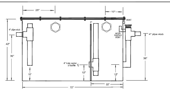
Custom Grease Traps
Hydromechanical Grease Interceptors James City County Va
Hydromechanical Grease Interceptors James City County Va
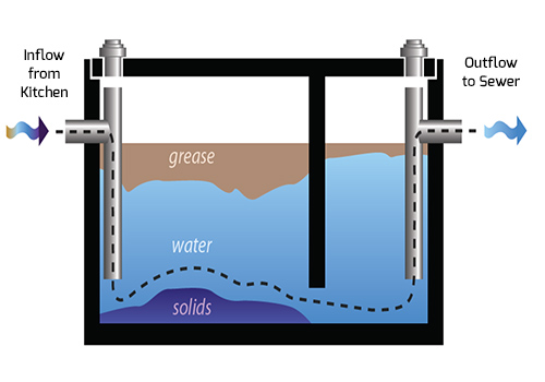
Grease Trap Services Cleaning Pumping Dar Pro Solutions

Grease Traps Avilas

Grease Trap
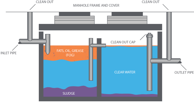
Grease Trap Vs Grease Interceptor Liquid Environmental Solutions

Hydromechanical Grease Trap Inspection Gallery Internachi
Grease Traps Help Protect Pipes But Have A Dangerous Side

National Committee On Urban Pest Control Training Institute Grease Trap Grease Trap Is A Receptacle That Kitchen Wastewater Flows Through Before Entering The Sanitary Sewer Lines This Receptacle Technically Defined As
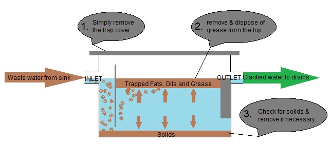
Grease Trap Diagram

Grease Interceptor 30 Lb 15 Gpm For Restaurant Plumbing Fog Management
_chamber.jpg)
How To Design Oil And Grease O G Chamber

Why Clean Grease Traps At Restaurants Matter Advanced Trenchless

Trapping And Venting For Grease Interceptors
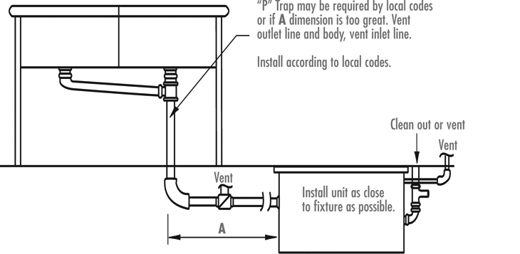
Installation Diagrams Rockford Separators
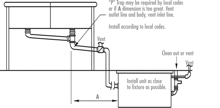
Installation Diagrams Rockford Separators